Design of 12-Hour Digital Clock
Demonstration of Circuit
Schematic of our Digital Clock
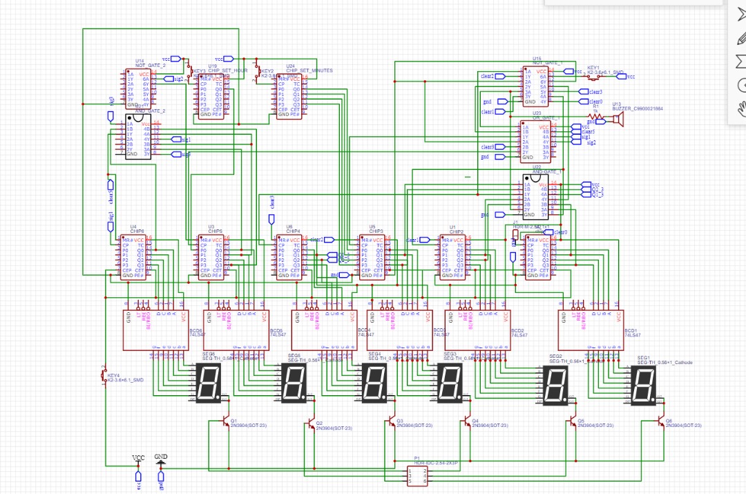
In this project we design a digital clock in logism, using the knowledge we gained from our Digital System Design class. For our clock we used the following components:
- 6 × 74161 modulo-15 counters
- 6 × BCD-to-7-segment decoder
- 6 × 7 segment display
- 1 × Buzzer
- 1 × 7805 Voltage regulator
- 1 × NE555 timer, configured for 2Hz
- Multiple resistors
- Multiple Capacitors
In our model the clock signal from the NE555 timer is sent to the BCD 74161 modulo-15 counter representing
seconds. Every time it has been clocked 10 times sends a signal to the 74161 IC in charge of 10s of seconds
and that is clocked. It moves a signal to the minute section whenever it has been clocked six times, since it
cannot exceed 60 seconds.
For the minute configuration it receives a clock signal from the 10s of seconds 74161, it follows the same logic
as the seconds section.
The hour section receives a clock signal from the IC in charge of the 10s of minutes. It logic is a bit different.
From the different minute and hour section because it is a 12 hour clock, hence it can only move from 0 to 12
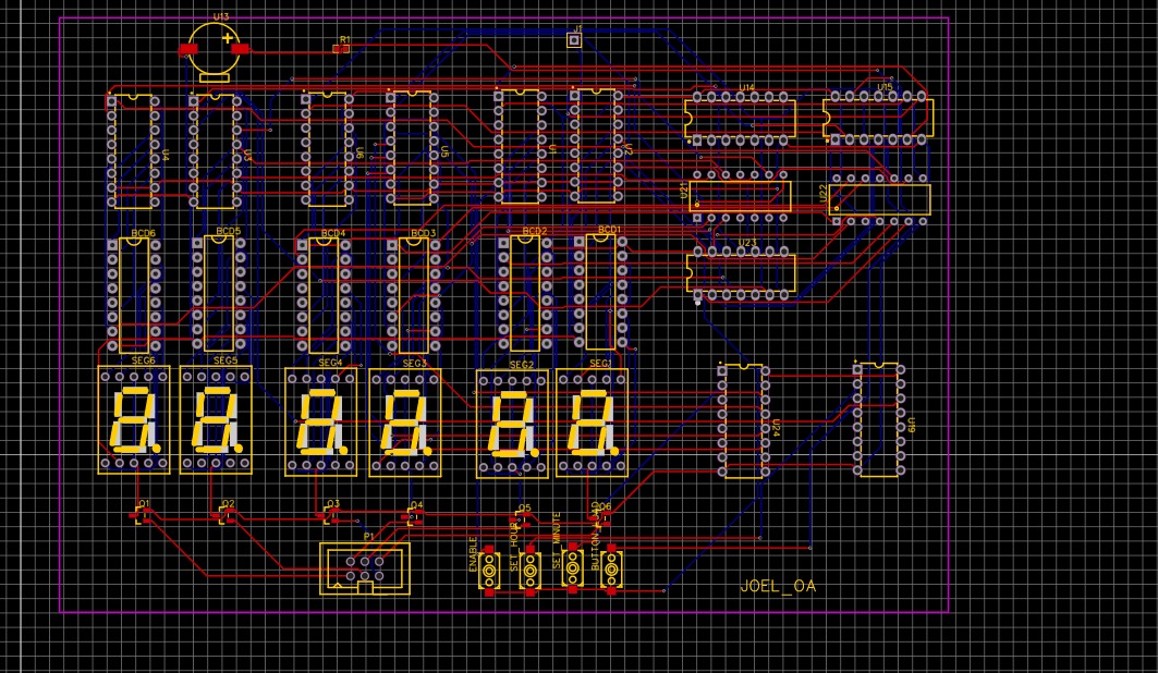
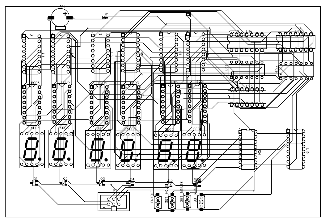
Below is the PCB designed by the team.
PCB Design